
So what is voltage anyhow? Well, its a pretty abstract term but a lot of people like to use the term "potential energy" which is that thing you heard about in high school physics and then forgot immediately.
Some people like to draw an analogy to water to describe voltage. A water pump is like a voltage supply (also known as a battery).
The pump pushes water through a hydraulic system, and the voltage supply pushes electrons through an electronic system.
The higher the rated pressure of the pump, the more 'work' the water can do.
Likewise, the higher the voltage the more 'work' (Watts) the electrons can do.
Voltage is used to provide power (via a battery or wall plug) and its also used as a way of transmitting data. For example, music is recorded from a microphone as an analog voltage signal, if that voltage waveform is applied to a speaker the voltage performs the work of making air move and produces sound.
Voltage is also used to in digital circuits to talk back and forth in binary, usually 5V or 3.3V is a "1" and 0V is a "0", by alternating the 1's and 0's millions of times a second, data can be moved around rather quickly.
AC/DC
Not just an 80's hair metal band! Voltage comes in two flavors (yum): Alternating Current (AC) and Direct Current (DC). Here is a quick tour of the differences.
Direct current voltage is what comes out of batteries. The battery is at 9V, and it pretty much keeps that voltage constant, until it dies. The chemical reactions inside the battery creates DC voltage.
Electronic circuits really like DC voltage.
Alternating current voltage is what comes out of the wall. The generator at the US power plant creates a voltage that oscillates, going from -120V to 0 to +120V to 0 again, 60 times a second. At the European power plant its -240V to +240V at 50 times a second. (Note that those voltages are 'RMS' - Root Mean Square - which means that the peak voltage is actually about 1.4x higher, but since multimeters show RMS voltages, its easier to just use those)
AC voltage is great for power plants because its easy to transform AC voltages (using a transformer) up to 50KV for long distance travel and then down to 240V or 120V to safely power your home. Those big honking grey things that you see next to buildings that hum are the huge transformers.
Motors (like your washing machine and refrigerator compressor pump) like running off of AC voltage.
You can turn AC voltage into DC voltage very easily by using a very small transformer to bring the 120V down to a reasonable level like say 16VAC and rectifier. This is basically what's inside a wall wart plug or your laptop power supply.
Its much harder to turn DC into AC, you will need an inverter which are more expensive than transformers/rectifiers.
Batteries only supply DC voltage and wall plugs only supply AC voltage. However, it is totally possible to have both AC and DC voltage at a certain point:
If an AC voltage is oscillating between -60V and +60V it has 120V AC and 0V DC because the average voltage of -60V and +60V is 0V.
If an AC voltage is oscilating between 0V and 120V then it has 120V AC and 60V DC because the average voltage of 0V and 120V is 60V.
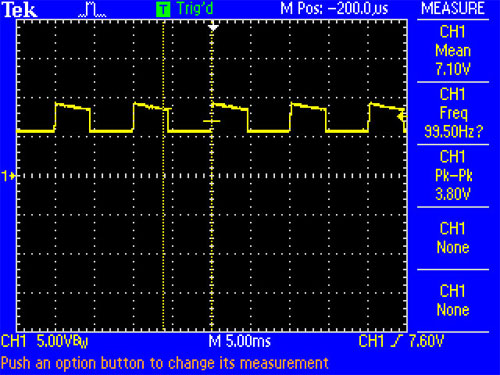
In the above oscilloscope image, the dashed horizontal line in the center is ground (0V) and each dashed division is 5V. The scope is displaying a signal that has both AC and DC components. There is an alternating voltage (a square wave) that is about 4V high at about 100Hz and a DC (mean average) voltage that is around 7V. Use the dashed divisions to verify for yourself that this is so.
What is voltage testing good for?
Voltage testing is very common, you'll use it a lot
- Test if your power supply is working, are you getting 5V out of that 7805 regulator?
- Verify that your circuit is getting enough power: when all of the blinky lights are on, is the power supply drooping too low?
- Verify signals to and from chips to make sure they are what you expect once the circuit is up and running
- Testing batteries, solar cells, wall plugs, and power outlets (carefully!)
- With a current sense resistor you can perform current testing on a project without possibly damaging your meter.
Remember!
You can only test voltage when the ciruit is powered If there is no voltage coming in (power supply) then there will be no voltage in the circuit to test! It must be plugged in (even if it doesn't seem to be working)
Voltage is always measured between two points There is no way to measure voltage with only one probe, it is like trying to check continuity with only one probe. You must have two probes in the circuit. If you are told to test at a point or read the voltage at this or that location what it really means is that you should put the negative (reference, ground, black) probe at ground (which you must determine by a schematic or somewhere else in the instructions) and the positive (red) probe at the point you would like to measure.
If you're getting odd readings, use a reference voltage (even a 9V battery is a reasonable one) to check your voltage readings. Old meter batteries and wonky meters are the bane of your existence but they will eventually strike! Good places to take reference voltages are regulated wall plugs such as those for cell phones. Two meters might also be good :)
Voltage is directional If you measure a battery with the red/positive probe on the black/negative contact and the black probe on the positive contact you will read a negative voltage. If you are reading a negative voltage in your ciruit and you're nearly positive (ha!) that this cannot be, then make sure you are putting the black probe on the reference voltage (usually ground)
DC voltage and AC voltage are very different Make sure you are testing the right kind of voltage. This may require pressing a mode button or changing the dial.
Unless otherwise indicated, assume DC voltages
Multimeters have different input impedences that affect readings of high impedence circuits For example, measuring a sensor that has 1Mohm impedence with a 1Mohm impedence meter will give you only half the correct reading
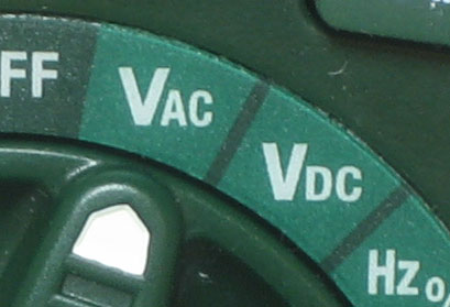
Get into the right mode
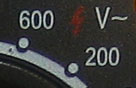
There are often two seperate modes for AC and DC voltage. Both will have a V but one will have two lines, one dashed and one solid (DC) and one with have a wave next to it (AC).
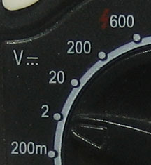

This meter has the double line for DC voltage, and 5 ranges, from 200mV to 600V. The lightning bolt symbol is a gentle reminder that this voltage is extremely dangerous.
There is also the V-wave symbol for AC, and two ranges since most AC voltages that are measured are power voltages and are pretty big. (For small AC waveforms, a scope is best since you will be able to see the waveform itself)
This autoranging meter makes it pretty clear which mode you want to be in
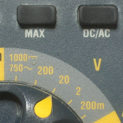
This ranged meter has 5 ranges, the top range is 750 VAC or 1000 VDC, to switch between DC and AC you need to press the DC/AC button on the upper right.
When the probes are not connected to anything, they should display 0V. They might flicker a bit if they pick up ambient voltage (your home is a big radiator of 60Hz voltage which can couple into your meter probes). 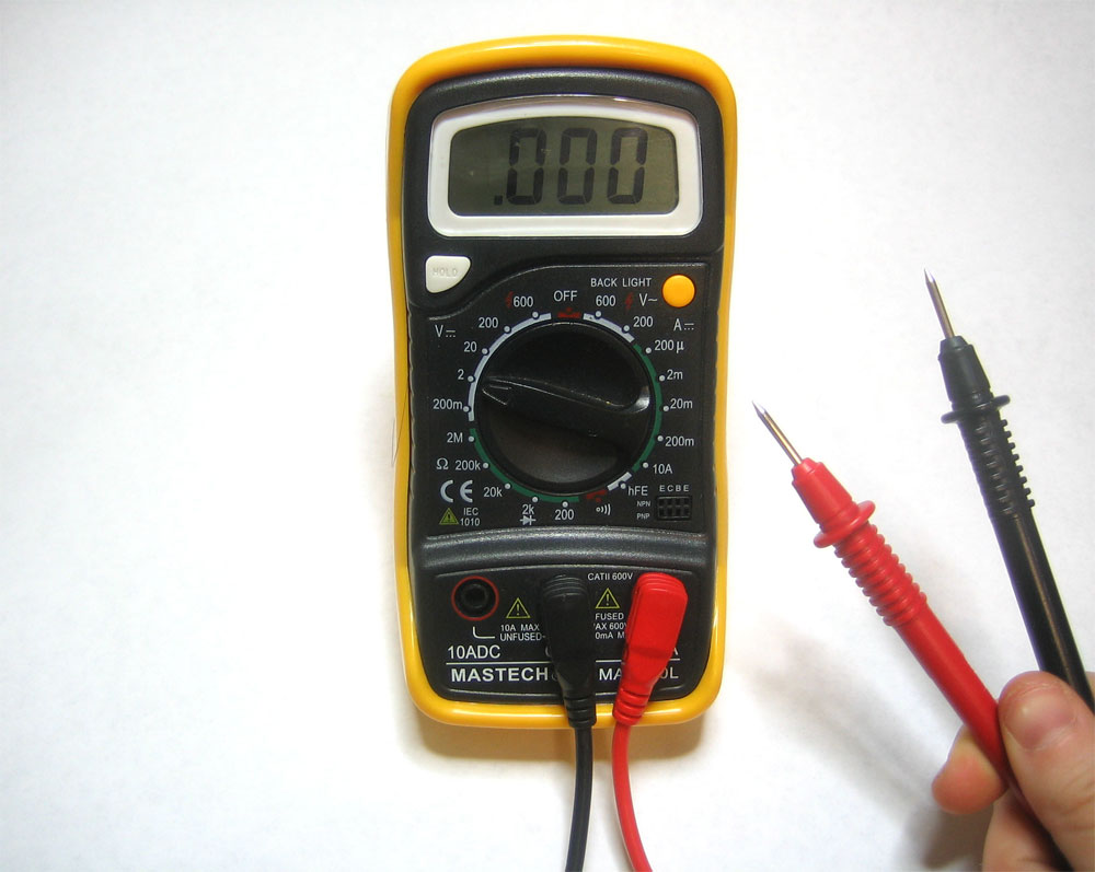
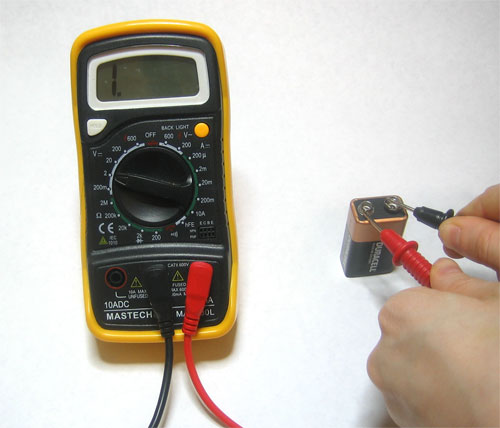
Example 1: Testing batteries
Testing batteries is a super useful skill and is one of the best ways to practice with your multimeter
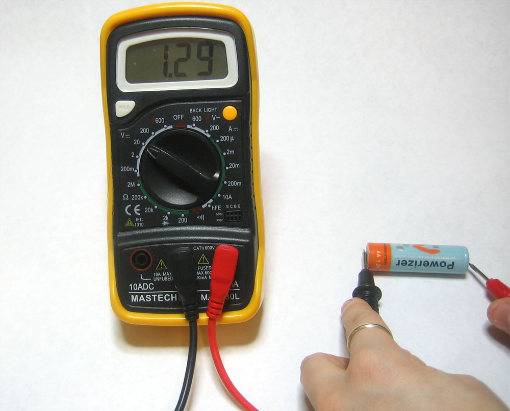
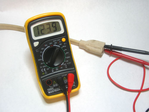
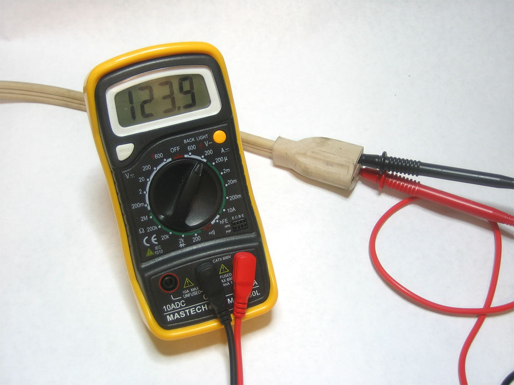
The first battery we'll test is a new 1.5V alkaline. This one is a AAA but a AA, C or D cell will be the same voltage. Set the range to 2V DC .
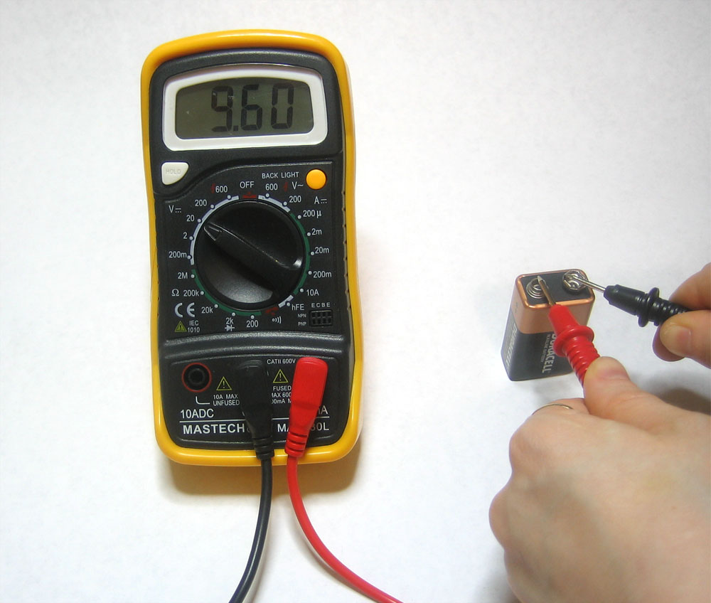
 For this new battery we get 9.6V. Remember that battery voltage is nominal, which means that the "9V" is just the average voltage of the battery. In reality, it starts out as high as 9.5V and then drops down to 9 and then slowly drifts to 7V. You can check out the discharge curve in the Duracell 9V datasheet
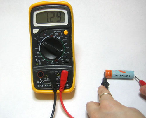
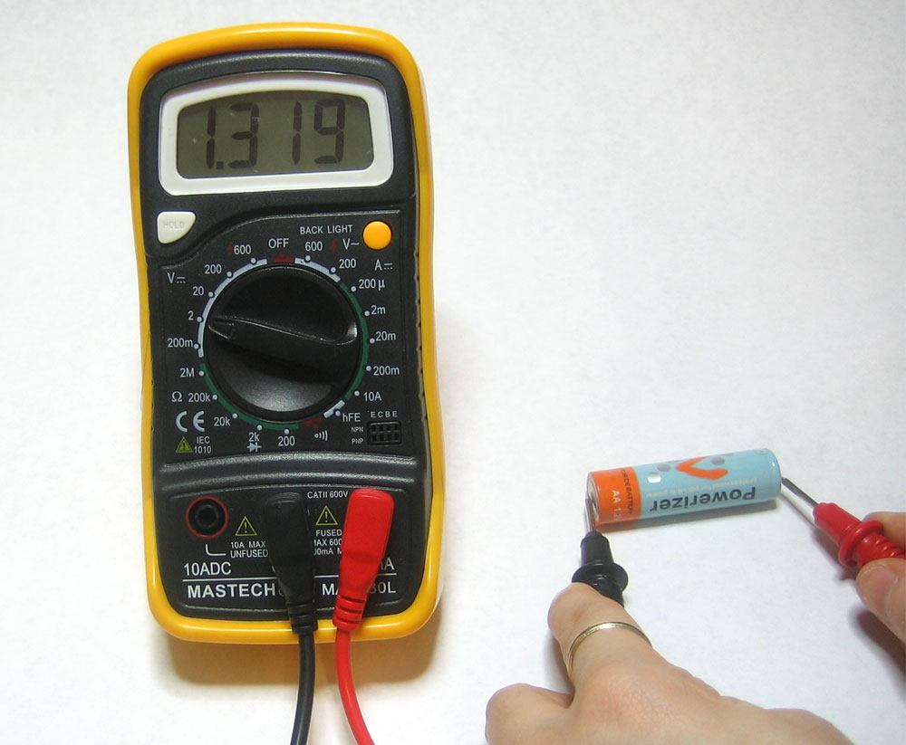
If we want to check a rechargeable AA battery, and it's set to a 20VDC range, we will read 1.3V, which is about what a fully charged NiMH battery will measure.

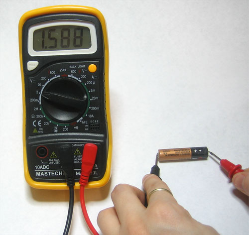
The first battery we'll test is a new 1.5V alkaline. This one is a AAA but a AA, C or D cell will be the same voltage. Set the range to 2V DC .
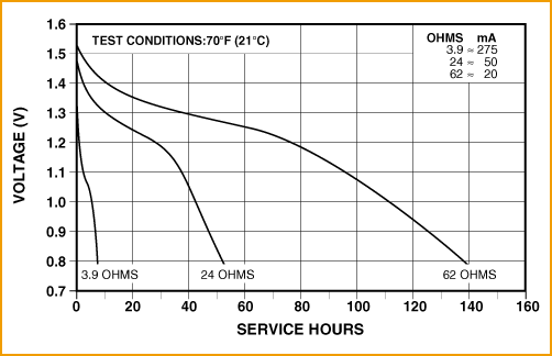
We read 1.588V, which you may think is a mistake, after all its a 1.5V battery so shouldn't it be 1.5V? Not quite, the 1.5V written on the side is just a nominal voltage, or the "average" you may expect from the battery.In reality, an alkaline battery starts out higher, and then slowly drifts down to 1.3V and then finally to 1.0V and even lower. Check out this graph from Duracell's page about alkaline battery voltage
Using this graph you can easy tell how fresh your battery is and how long you can expect it to last.
Next, we measure a 9V alkaline battery. If we still have the range set to 2VDC we will get a mysterious "1. " display, indicating is it over-range. Fix the range so that it's 20V, and try again.
If we want to check a rechargeable AA battery, and it's set to a 20VDC range, we will read 1.3V, which is about what a fully charged NiMH battery will measure.
If we fix the range so it's 2VDC, we can get an extra digit of precision. This meter probably isnt more than 0.5% accurate so the precision may not mean much.
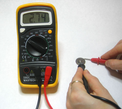
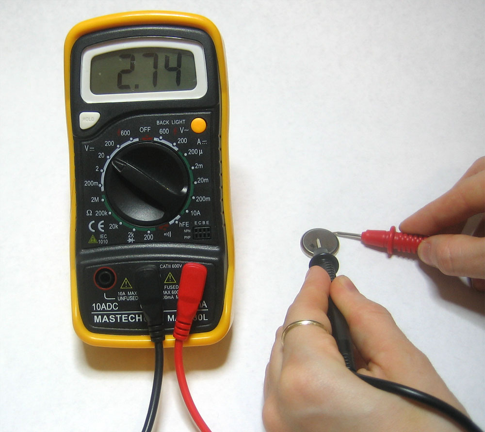
Finally, I test a lithium 3V coin cell, its at 2.7V which means it's getting near the end of it's life.
Example 2: Testing wall wart (adapter) plugs
Testing wall adapters is also very handy, especially when you build your own circuits.
The first kind we will test is a transformer-based adapter.

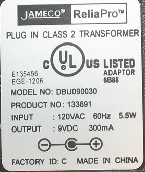
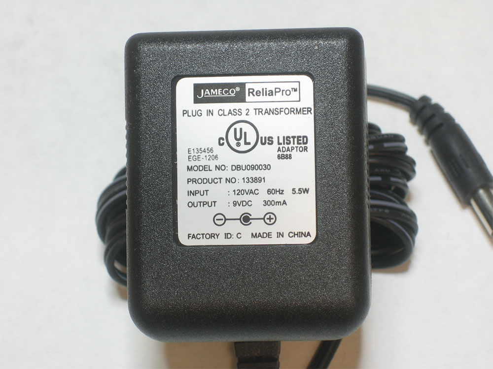
This photo has notes. Move your mouse over the photo to see them. Note that the label says Transformer, its also blocky and heavy which indicates a transformer as well. It requires 120VAC input, US power only. The nominal output is 9VDC at 300mA. The polarity symbol shows that the middle is positive, the outside is negative, thus we place the ground (black) probe on the outside and the positive (red) probe on the inside.

This photo has notes. Move your mouse over the photo to see them.
Lastly, we'll test a 9VAC adaptor, which outputs AC voltage instead of DC. Basically this means that there's still a transformer inside, but no rectifier. This is also an unregulated supply

This photo has notes. Move your mouse over the photo to see them.
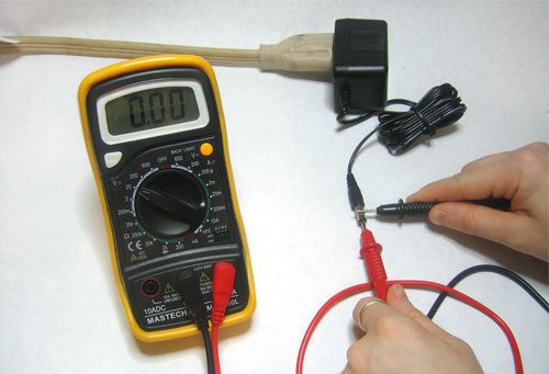
The first kind we will test is a transformer-based adapter.
This photo has notes. Move your mouse over the photo to see them.
Note that the label says Transformer, its also blocky and heavy which indicates a transformer as well. It requires 120VAC input, US power only. The nominal output is 9VDC at 300mA. The polarity symbol shows that the middle is positive, the outside is negative, thus we place the ground (black) probe on the outside and the positive (red) probe on the inside. 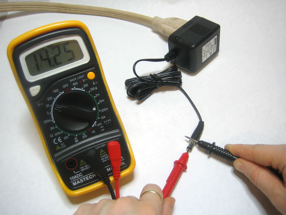
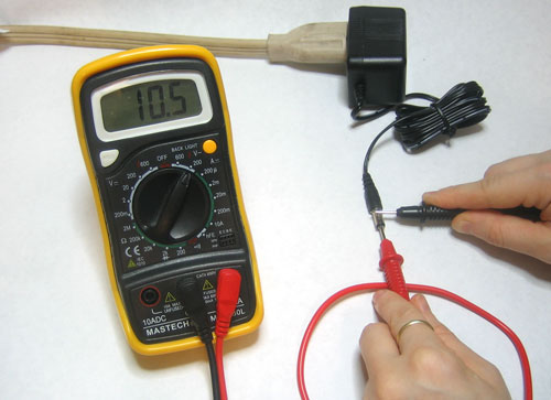
Yow! 14V? That's not anything like the 9V on the package, is this a broken wall wart? Turns out, its totally normal. Transformer-based wall adaptors are (almost always) unregulated, which means that the output is not guaranteed to be a particular value, only that it will be at least what is printed on the box. For example, with this adapter it means that when drawing 300mA, the voltage is guaranteed to be higher than 9V.
Since the output is unregulated, the voltage supplied will droop as more current is pulled from it, which means that open-circuit (connected to nothing) the measured output can be as high as 14V. Glitchbuster has a long page that describes this.
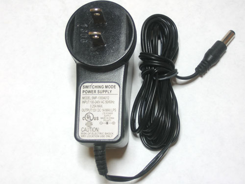
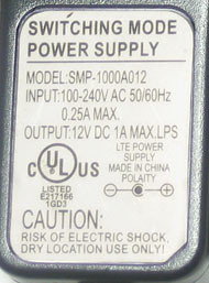
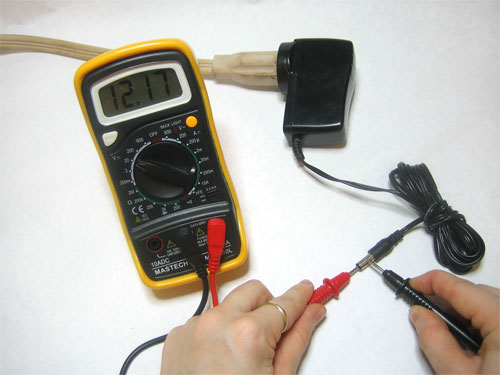
Next, lets check out a Switch-mode adapter

Notice that it's not square, its much thinner and although you cant feel it, its quite light for its size: There is no big honking transformer inside!
This photo has notes. Move your mouse over the photo to see them.
Note that it says Switching (not Transformer) on the label, and you can input US or European power. Like the transformer adapter, it is center-positive polarity.

Switch-mode wall adapters are regulated which means that the output doesn't droop from open-circuit to full load. Its not an ultra-high quality supply, the voltage is 12.2V which is less than 5% error. Still, its much better than the transformer's 50% error!
Note that is is similar to the transformer-based DC supply we checked out first
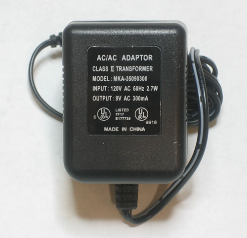
This photo has notes. Move your mouse over the photo to see them.
Note again that the label says transformer. It requires 120VAC input, US power only. The nominal output is 9VAC at 300mA. The output is indicated twice, once at the top "AC/AC" and then again in the output designator "9V AC"
There is no polarity because AC adaptors are not polarized: AC power oscillates between positive and negative voltages.
There is no polarity because AC adaptors are not polarized: AC power oscillates between positive and negative voltages.
We test the output, but get 0V! That's when we remember that the multimeter has to be in AC voltage mode.

Switching over to AC, we get a good reading, 10.5VAC. This is an unregulated supply so again we are going to get a voltage higher than 9V.

Example 3: Testing Wall output
This is the 'easiest' test, just shove the two probes into a wall socket. If you're clumsy and think you'll somehow electrocute yourself, don't do this. Many people freak out about this test, but ironically it's what the multimeter was designed to do.
About 120V, as expected
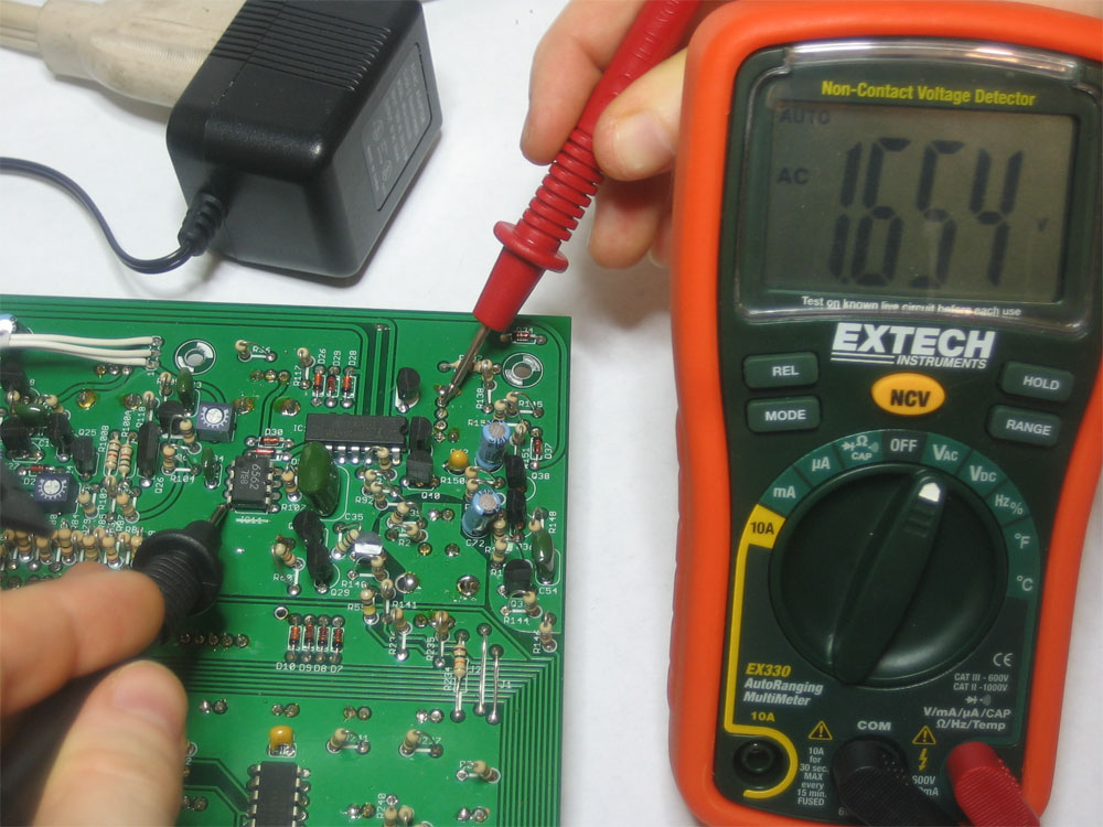
Bonus Example: Testing a circuit with AC and DC
If you're trying to measure something that is just DC or just AC its very easy, just get into the right mode and measure away! The hardest thing to do is measure a circuit with both AC and DC voltages.For example, here is a few attempts to measure the VCO output of a x0xb0x as seen in the oscilloscope output shown here (its the same one from above
The DC portion is the easy part to measure, most multimeters just average out the input measurement
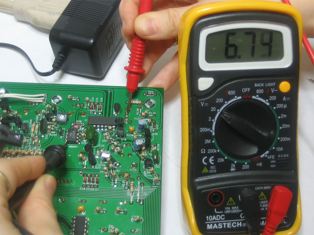
We read 6.75V DC, which is about right.
However, when trying to measure AC, this multimeter gives us a seemingly random number. (Maybe the DC voltage * 2 ?)
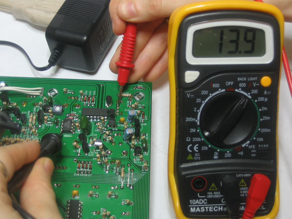
The Wavetek does the same
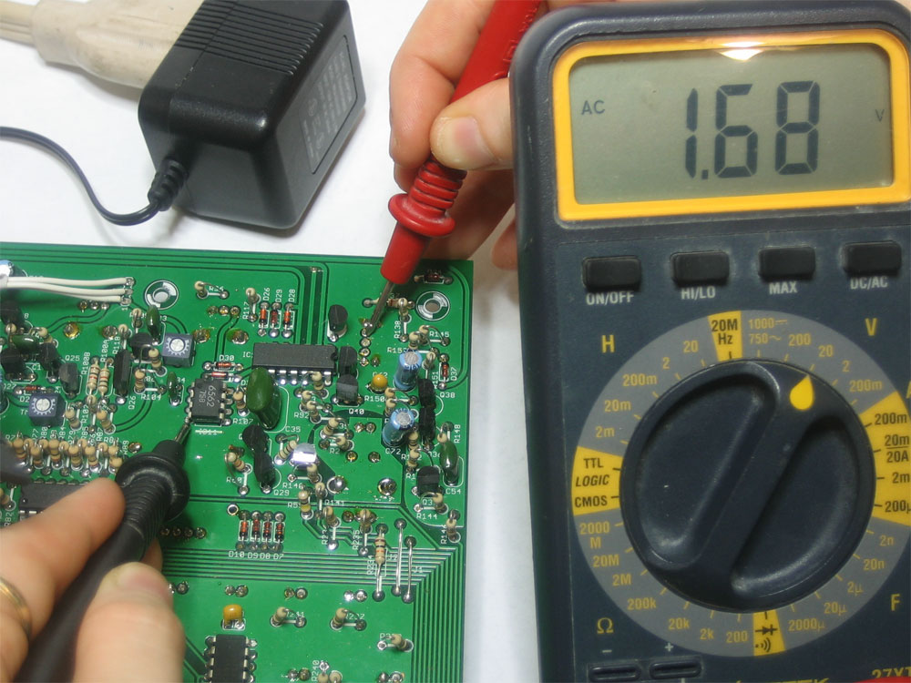
The lesson? You can't depend on your multimeter to measure AC voltages when there is a DC component!
REFERENCES
http://www.ladyada.net/learn/multimeter/voltage.html
http://www.youtube.com/watch?v=KzjMIcER4EU
http://www.multimeterwarehouse.com/usingamultimeter.htm